Our approach to parts design and engineering follows a systematic four-step methodology, integrating key disciplines like engineering design, 3D mold design, tooling design, and mould DFM (Design for Manufacturability) design to ensure optimal functionality and manufacturability.
Conduct the feasibility study for the part's application scenarios, such as mechanical load, environmental conditions (temperature, corrosion) and industry standards (automotive, medical).
Collaborate with clients to establish a detailed requirements list, covering dimensional tolerances, surface finishes, and performance metrics. This stage lays the groundwork for integrating 3D molddesign and tooling design considerations early on.
Identify potential manufacturability challenges through preliminary mould DFM design reviews, ensuring design concepts are feasible for production.
Evaluate material candidates (plastics, metals, composites) based on part functionality, cost, and production volume. For example, high-strength alloys for tooling design in injection molding or engineering polymers for lightweight components.
Recommend manufacturing technologies (CNC machining, 3D printing, injection molding) that align with 3D mold design needs. For instance, selecting SLA 3D printing for complex prototypes or H13 steel for durable injection molds.
Provide engineering consultation to balance performance with cost-effectiveness, integrating mould DFM design principles to minimize post-production adjustments.
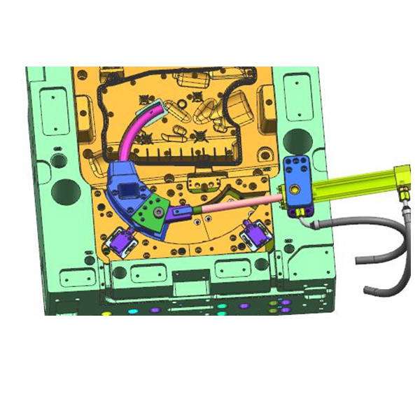
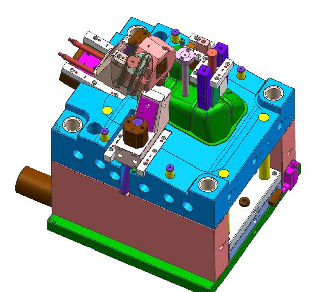
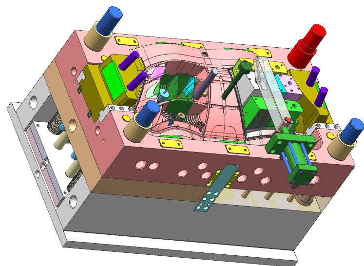
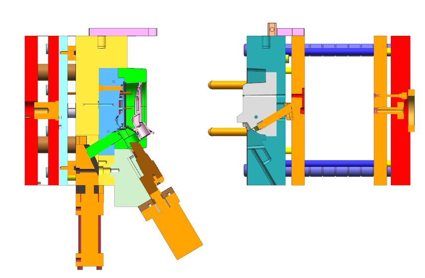
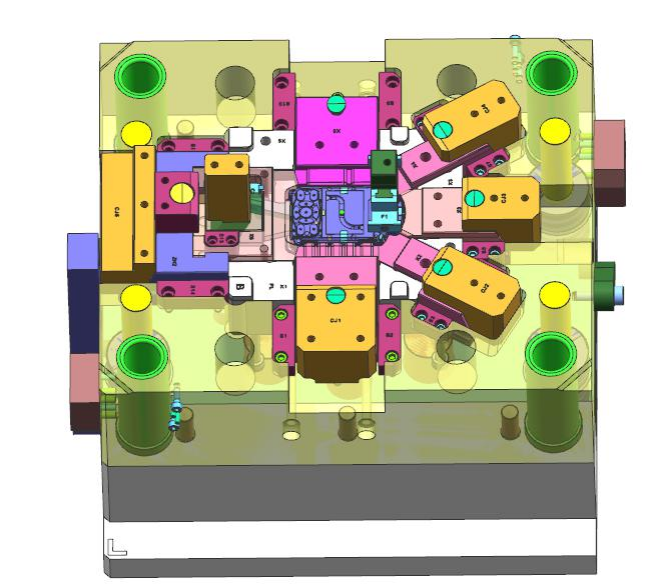
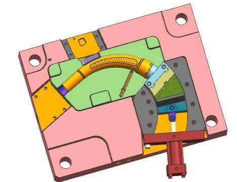
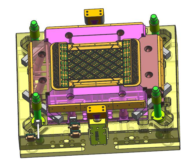
Create 3D parametric models using software like SolidWorks or UG, incorporating 3D mold design elements such as parting lines, draft angles, and cooling channels directly into the part geometry.
Develop detailed 2D engineering drawings with GD&T (Geometric Dimensioning and Tolerancing) specifications, ensuring alignment with tooling design requirements for mold fabrication.
Perform virtual simulations (finite element analysis, mold flow analysis) to validate design integrity, identifying stress concentrations or filling issues early in the 3D mold design process.
Integrate mould DFM design feedback from manufacturing teams to optimize wall thickness, rib placements, and undercuts for seamless mold production.
Produce functional prototypes via 3D printing (SLA, SLM), CNC machining, or prototype tooling design (soft molds), ensuring they reflect 3D mold design intent.
Conduct physical testing (fit, form, function) to validate design performance, collecting data for iterative improvements. Prototypes also serve as references for tooling design teams to refine mold specifications.
Incorporate mould DFM design insights from prototyping into the final design, addressing issues like ejection feasibility or surface finish consistency before committing to production tooling.
Deliver prototypes alongside detailed reports, guiding clients on how to transition designs into full-scale manufacturing with optimized tooling design and 3D mold design parameters.