

The basic structure of any injection mold consists of two halves: the fixed mold and the movable mold. The fixed half mounts rigidly on the stationary platen of an injection molding machine, while the movable half attaches to the reciprocating platen. This fundamental configuration supports advanced systems such as precision plastic injection molds, multi cavity hot runner mold systems, gas assisted mold technology, and collapsible core molds. Understanding how each structural type operates—with specific parameters and performance data—helps manufacturers select the right tool for complex parts, reduce cycle times, and avoid costly design errors.
1. Fixed and Movable Mold Halves: The Foundation of Any Injection Mold
Every injection mold relies on precise alignment between fixed and movable halves. During operation, hydraulic clamping systems generate 500 to 5000 tons of locking force to keep the mold closed during injection. Precision guide columns with a diameter of 20–50 mm and straightness tolerance ≤ 0.01 mm/m ensure that the injection mold maintains alignment over millions of cycles.
Key Data:
Clamping force range: 500 – 5000 tons
Guide column straightness: ≤0.01 mm per meter
Mold steel hardness: HRC 50–55 for precision applications
For a multi cavity hot runner mold, uniform melt distribution is critical. Heated manifolds keep the plastic temperature variation ≤ ±3°C across all cavities. Without this thermal balance, an injection mold with 8 or 16 cavities will produce dimensional rejects.
2. Precision Plastic Injection Molds: Achieving Tolerances of ±0.005 mm
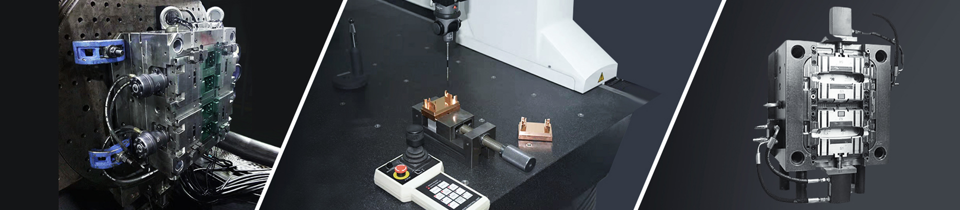
When component geometry demands micron-level accuracy, precision plastic injection molds are the only solution. These molds use hardened tool steels (HRC 50–55) and fine-finished cavity surfaces with Ra < 0.8 μm. Typical achievable tolerances: ±0.005 mm for critical dimensions.
Why choose precision plastic injection molds?
Medical device housings require ±0.01 mm on snap-fit features.
Electronic connectors demand ±0.005 mm on pin spacing.
Vibration dampening and temperature control (±1°C) are mandatory.
A precision plastic injection mold also incorporates IoT sensors that track clamp force, melt pressure, and cavity temperature in real time. This data reduces scrap rates by 20% compared to conventional molds. For a production run of 1 million parts, that saving alone justifies the higher initial tooling cost.
3. Multi Cavity Hot Runner Mold: High-Volume Efficiency with Thermal Uniformity
A multi cavity hot runner mold eliminates cold runners, reducing material waste by 15–35%. The hot manifold system maintains melt temperatures between 180°C and 320°C with a uniformity of ΔT ≤ 3°C across all drops. This is essential for consumer goods, packaging, and automotive interior parts.
Operational parameters for a multi cavity hot runner mold:
Number of cavities: typically 4, 8, 16, 32, or 64
Runner balance: flow variation ≤ 2% between cavities
Cycle time reduction: 20–40% compared to cold runner molds
For a 32‑cavity multi cavity hot runner mold producing bottle caps, the cycle time can drop from 12 seconds to 8 seconds, increasing daily output by 50,000 units. However, runner balance must be validated with mold flow analysis—otherwise, some cavities will short‑shot while others flash.
4. Gas Assisted Mold: Weight Reduction and Sink Mark Elimination
A gas assisted mold injects nitrogen gas (pressure: 5–20 MPa) into the melt after partial filling. The gas hollows out thick sections, reducing part weight by 15–30% and eliminating sink marks without adding cycle time.
Typical applications of a gas assisted mold:
Automotive bumpers (weight reduction: 2.5 kg per part)
Office chair armrests (sink mark elimination)
Large appliance handles (improved rigidity)
Gas injection timing is critical: 0.5–1 second after injection starts. Residual gas pressure (1–2 MPa) at the end of cooling assists in part ejection. Compared to conventional injection mold designs, a gas assisted mold requires additional valve gates and gas channels, but the material savings often pay back tooling cost within 3–6 months.
5. Collapsible Core Molds: Releasing Undercuts Without Secondary Operations
For parts with internal undercuts, threads, or recesses, collapsible core molds use hydraulic or pneumatic actuators to retract segmented cores. Typical retraction tolerance: ±0.02 mm. Core retraction speed is adjustable between 0.1 and 0.5 m/s, preventing part deformation.
Why specify collapsible core molds?
Pipe fittings with internal threads: no unscrewing mechanism needed
Appliance handles with grip recesses: eliminated secondary machining
Automotive fluid connectors: consistent sealing surfaces
A collapsible core mold can integrate with a multi cavity hot runner mold for high‑volume production of complex parts. For example, an 8‑cavity tool producing 90° elbow fittings uses collapsible core molds on each cavity, achieving a cycle time of 25 seconds versus 45 seconds with traditional unscrewing molds.
Comparison: Which Injection Mold Structural Type Solves Your Problem?
| Mold Type | Key Parameter | Typical Application | Advantage |
|---|---|---|---|
| Precision plastic injection molds | Tolerance ±0.005 mm | Medical devices, electronics | Micron accuracy |
| Multi cavity hot runner mold | Temp variation ≤±3°C | Packaging, consumer goods | 20‑40% faster cycles |
| Gas assisted mold | Gas pressure 5–20 MPa | Automotive bumpers, chairs | 15‑30% weight reduction |
| Collapsible core molds | Core retraction 0.1–0.5 m/s | Pipe fittings, handles | Eliminates unscrewing |
| Standard injection mold | Locking force 500–5000 t | General parts | Lowest tooling cost |
Cooling, Ejection, and Safety: Data-Driven Improvements
Regardless of the structural type, every injection mold requires efficient cooling. Conformal cooling channels (diameter 8–12 mm) maintain uniform mold temperature with ΔT ≤ 5°C, cutting cycle time by 15% in multi cavity hot runner mold applications. Cooling time typically ranges from 10 to 40 seconds depending on wall thickness.
Ejector pins (diameter 4–10 mm) powered by hydraulic cylinders push the part out. In a gas assisted mold, residual nitrogen pressure helps release the part, reducing ejection force by 30–50%.
Safety interlocks using proximity sensors ensure the injection mold is fully closed before injection—this prevents material leakage, especially critical for precision plastic injection molds where flash would ruin tight tolerances.
Conclusion: Selecting the Right Injection Mold Structural Type
Choosing between collapsible core molds, gas assisted mold systems, precision plastic injection molds, and a multi cavity hot runner mold depends on part geometry, annual volume, and tolerance requirements. For undercuts, collapsible core molds are the only efficient method. For thick sections, a gas assisted mold reduces weight and sink marks. For high‑volume precision parts, precision plastic injection molds with IoT monitoring deliver scrap rates below 2%. And for maximum productivity, a multi cavity hot runner mold balances thermal uniformity across 32+ cavities.
Longterm Manufacturing Solutions Ltd. engineers all five structural types with documented performance data—from guide column straightness to gas injection timing. Contact us to review your part design and receive a technical recommendation based on cycle time, material savings, and tool life.
Contact for Inquiries:
Longterm Manufacturing Solutions Ltd.
Tel: +86 156 0239 2025
Email: longterm@longterm-mold.com
Website: www.longterm-mold.com
For technical datasheets, mold flow analysis samples, or a consultation on injection mold structural types, reach out to our engineering team.
