

Shenzhen, China – June 15, 2026 – Longterm Mold today detailed its end-to-end manufacturing framework that unifies product design and development, precision 3D part design, detailed Part CAD design, iterative part development, and mechanical product design and development into a single, traceable process. The structured five-stage system targets OEMs and product companies that require high-precision molded components and need to eliminate the frequent misalignment between concept models and production-ready parts.
product design and development Anchored in Functional Requirements
The company’s product design and development phase starts with quantified market research and functional analysis. Before any digital model is created, the team defines load conditions, thermal exposure, chemical contact, and lifecycle targets. This upfront product design and development discipline ensures that subsequent 3D part design and Part CAD design work is grounded in measurable performance requirements rather than assumptions. A typical early-phase product design and development cycle produces a requirement specification with 40–60 defined parameters, which directly feeds the mechanical product design and development roadmap.
3D part design and Part CAD design with Simulation-Linked Modeling
Within the digital engineering stage, Longterm Mold applies parametric 3D part design using SolidWorks, AutoCAD, and Siemens NX. Every 3D part design dataset integrates tolerance zones (commonly ±0.01 mm for critical interfaces) and surface finish callouts. Parallel to 3D part design, the team builds complete Part CAD design assemblies that include gate locations, ejection layouts, and cooling channel architectures. A dedicated Part CAD design review incorporates mold flow simulation and finite element analysis (FEA) to stress-test the 3D part design before tool steel is cut. For a recent mechanical product design and development project, FEA-driven 3D part design iterations reduced post-tooling geometry adjustments by 32% compared to the initial baseline.
The deliverables from this stage include:
Full 3D part design master models with revision-controlled geometry.
Part CAD design packages containing core, cavity, slider, and lifter definitions.
Simulation reports that link the 3D part design behavior to process parameters.
part development Through Tooling and Process Verification
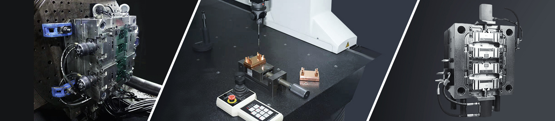
Longterm Mold treats part development as a combined tooling and process-parameter exercise. Mold manufacturing begins only after the Part CAD design freeze. Tool steels – typically P20 for medium runs and H13 for high-volume mechanical product design and development programs – are machined on five-axis CNC centers and finished with EDM where required. Mold hardness is verified at HRC 50–65 depending on the part development specification. The physical part development validation loop includes dimensional inspection on CMM equipment, with reports aligned to the 3D part design nominal. During this part development phase, any deviation greater than 0.02 mm triggers a DFM review that loops back into the Part CAD design environment. This tight coupling of part development and Part CAD design ensures that the final mold consistently delivers parts matching the original product design and development intent.
mechanical product design and development Optimization at Production Scale
Once the mold is qualified, Longterm Mold transfers the mechanical product design and development data into production monitoring. Injection molding machines run parameter sets derived from the earlier part development trials, with cavity pressure transducers and thermal imaging used to maintain process stability. Automated inspection systems capture 100% of produced parts and compare each to the 3D part design tolerance envelope. In a recent automotive mechanical product design and development engagement, this data loop reduced out-of-tolerance events to below 0.3% of the total batch. The production team continuously refines the mechanical product design and development workflow based on SPC data, which can trigger minor Part CAD design adjustments for longevity or cycle time reduction.
Post-Production mechanical product design and development and Lifecycle Support
After mass production launch, Longterm Mold provides complete documentation sets: the frozen Part CAD design files, mold maintenance logs linked to cycle counts, and inspection data cross-referenced to the 3D part design baseline. When a customer’s product design and development roadmap requires a variant, the existing Part CAD design serves as the starting point for the next part development spiral, preserving all validated mechanical product design and development parameters. This documentation continuity turns a single product design and development project into a reusable asset for future product design and development cycles.
Key performance benchmarks observed across programs:
3D part design-to-mold-ready cycle compressed by 27% when simulation and Part CAD design are run concurrently.
part development approval rate after the first tooling trial: 89% for projects following the full product design and development workflow.
Average dimensional capability index (Cpk) achieved: 1.47, validated against 3D part design specifications.
Mold life extension: H13 molds managed under the structured part development and Part CAD design revision process exceed 500,000 cycles in documented mechanical product design and development cases.
Consult with Longterm Mold
To discuss a specific product design and development initiative or to review a 3D part design and Part CAD design package for an upcoming part development project, contact Longterm Mold directly.
Tel: +86 156 0239 2025
Email: longterm@longterm-mold.com
Website: www.longterm-mold.com
