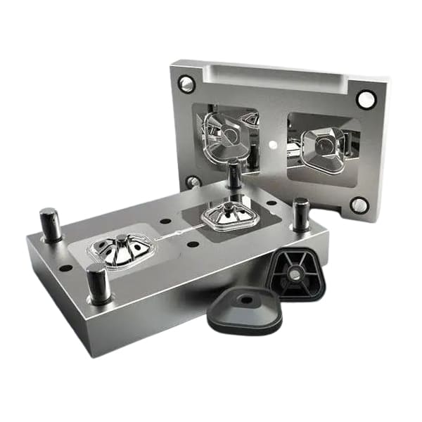
Injection molding dies consist of two main assemblies: the stationary half, which bolts to the machine’s fixed platen, and the moving half, attached to the reciprocating platen. Beyond this fundamental split, advanced mold designs—such as collapsible core systems, gas-assist tooling, precision molds, and multi-cavity hot-runner assemblies—add targeted functions to meet challenging part requirements.
Core Assembly and Mounting
• Stationary Half: Secured rigidly on the fixed platen; incorporates the sprue bushing and half the cavity geometry.
• Moving Half: Fastened to the injectors’ sliding platen; houses ejector mechanisms and completes the cavity.
Accurate alignment between these two halves is the bedrock of high-precision operations.
Closing, Guidance & Clamping
• Guide Posts: Typically Ø20–50 mm hardened columns with straightness within 0.01 mm/m direct the moving half into perfect registration.
• Clamping System: Hydraulic or toggle units develop forces from 500 to 5 000 tons, ensuring no flash forms when filling high-pressure or multi-cavity hot-runner molds.
Melt Delivery and Injection
4.1 Flow Path
– Melt (180–320 °C) exits the machine nozzle, traverses the sprue and runner network, then enters the cavity through the gate.
– In hot-runner configurations, the manifold is temperature-controlled to within ±3 °C across all feedlines for uniform filling.
4.2 Gas-Assist Feature
– After the resin pack, nitrogen (5–20 MPa) is injected to form hollow sections, cutting part mass by up to 30 % and eliminating sink marks in thick zones.
Specialized Mold Variants
5.1 Collapsible Core Molds
• Retractable Core Pins: Actuated hydraulically or pneumatically (±0.02 mm accuracy) to free undercut features—ideal for complex automotive or appliance parts.
5.2 Precision Injection Molds
• Ultra-Tight Tolerances: Achieved by using hardened tool steels (HRC 50–55) and polishing to surface finishes below Ra 0.8 µm, holding dims to ±0.005 mm.
5.3 Multi-Cavity Hot-Runner Molds
• Balanced Feed: Manifold design and nozzle selection ensure equal melt distribution, critical for high-volume consumer goods and packaging components.
Cooling and Part Ejection
• Conformal Channels: 8–12 mm diameter circuits built close to the cavity maintain ΔT ≤5 °C, speeding cycle times.
• Ejection: Following a 10–40 s cooldown, hydraulic ejector pins (Ø4–10 mm) push finished parts out. In gas-assist molds, residual gas aids release.
Performance Metrics by Mold Type
Mold Type Key Parameter Applications
Collapsible Core Retraction speed: 0.1–0.5 m/s Pipe fittings, ergonomic handles
Gas-Assist Gas-injection delay: 0.5–1 s Bumpers, chair shells
Precision Molds Thermal stability: ±1 °C Medical, electronic housings
Multi-Cavity Hot-Runner Flow balance & thermal uniformity Packaging, mass-market parts
Safety & Process Control
• Mold-Close Interlocks: Sensors prevent injection until full closure is confirmed, removing leakage risk.
• Real-Time Monitoring: IoT probes log clamp tonnage, melt pressure and temperature—cutting scrap by up to 20 %.
Summary
By integrating precise guidance, robust locking, and purpose-built features—collapsible cores, gas channels, fine-tolerance cavities and hot-runner manifolds—modern injection molds deliver complex, high-quality plastic parts efficiently and consistently, powering innovations across automotive, medical, electronics and consumer industries.

